Features :
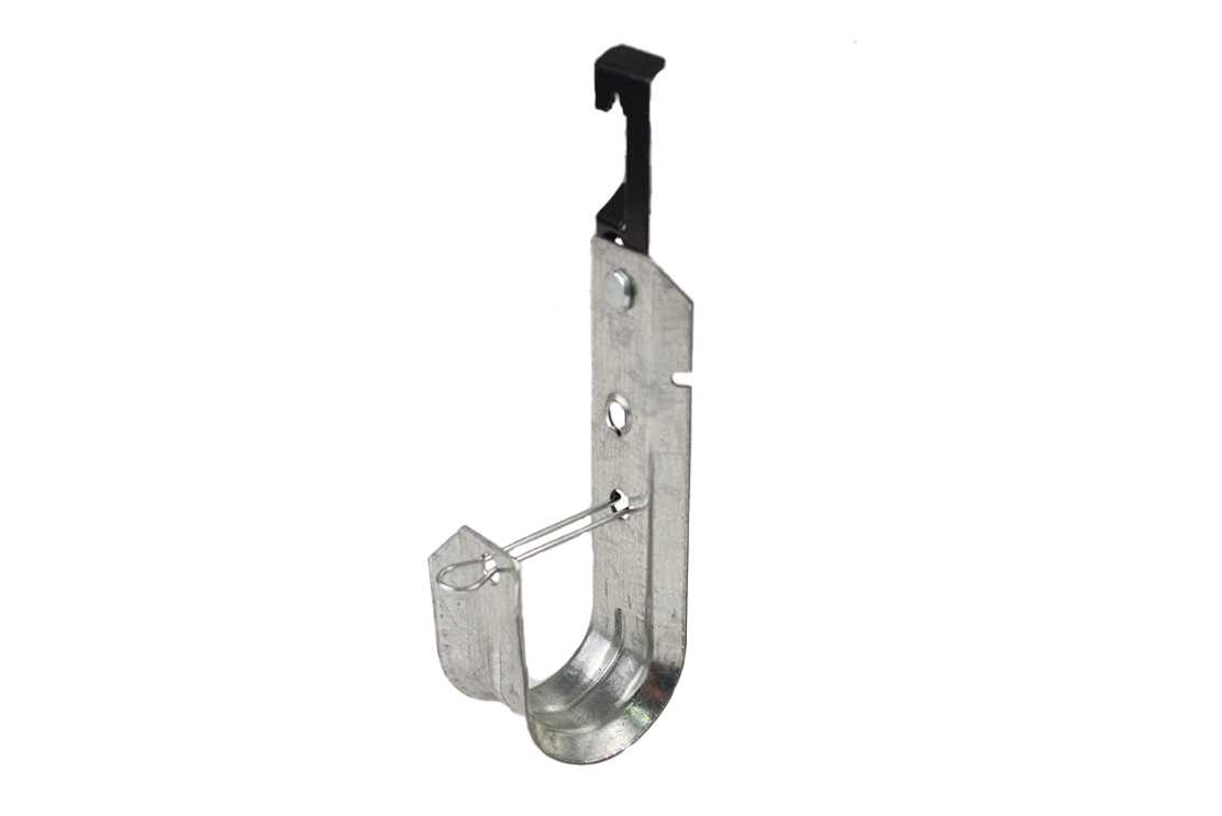
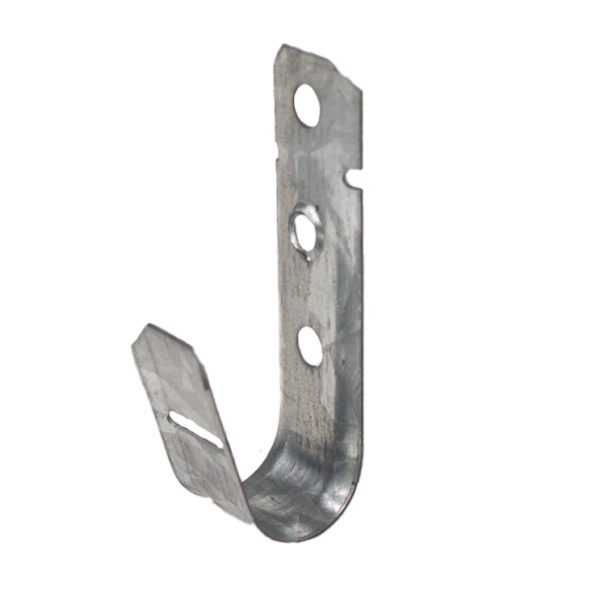
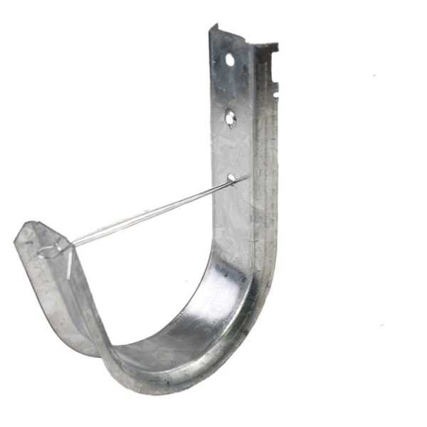
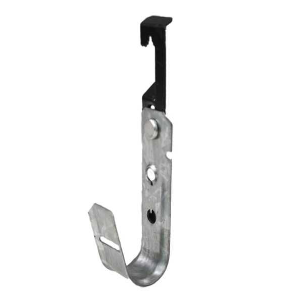
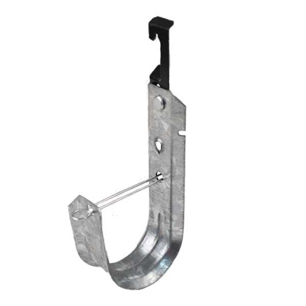
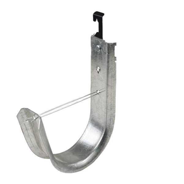
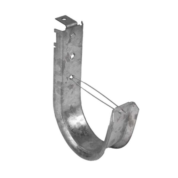
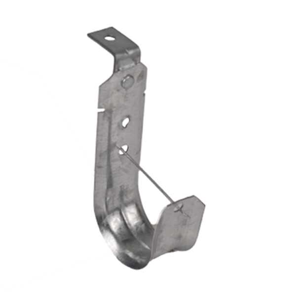
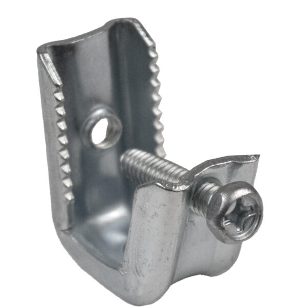
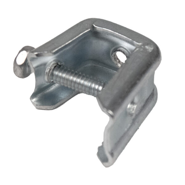
- J-Hook, 1 5/16″ with Wing
- Pre-Galvanized Steel
- Rust Resistant Zinc Coating
- Winged Hook Mounts on Vertically Spanning Steel Cable
- Load Capacity 60 lbs (for more information on load capacity, see the chart below)
- #12 Shaped Wing Attaches to 1/4in Vertical Rod
- Holder Secures Cable
- Thickness: 0.05 in. (1.35 mm)
- Weight: 0.15 lbs (70 g)
Mechanical capacity:
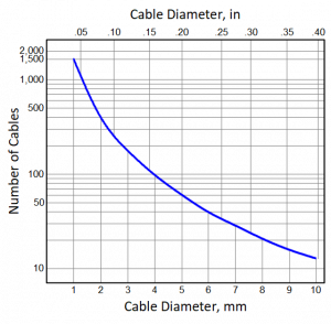
NOTE: The capacity chart provided above shows maximum possible values calculated based on the geometry parameters of the J-hooks. In real life installations, due to imperfection of cable bundles and variable paths cables take within the bundles, actual J-hook’s capacity could be lower and reach 50 % of the maximum as the worst-case scenario, the uncertainty grows as the number of cables placed on the J-hook grows. Typical recommended quantity reduction should be 25 % against the values provided in the graphs.
Additional limitations on discrete support load and capacity established by codes and standards:
- For all power and power-limited cables, please, refer to the requirements set up in NFPA 70, National Electrical Code (NEC).
- For all twisted-pair and optical fiber cables, follow the following guidelines set up by TIA and BICSI standards and manuals:
BICSI ITSIMM 8th Ed.:
- Open-top cable supports (e.g., J-hooks) … should not be used for installations of more than 50 cables. Do not overload open-top cable supports by using plastic cable ties to retain additional cables. Open-top cable supports should be attached to the building structure and installed on a center spacing varying between ≈1.2 m (4 ft) to ≈1.5 m (5 ft). These cable supports shall not be painted nor used for purposes not intended. Where not specified by the AHJ, open-top cable supports should be installed to maintain a minimum of ≈75 mm (3 in) vertical clearance between the cabling and cable supports and elements such as ceiling tiles, electrical conduit, luminaires, and piping and ducting. Open-top cable supports shall not be attached to a ceiling grid support system but may require a secondary connection to the ceiling grid to prevent lateral movement of the supports. No single support device should exceed the manufacturer’s recommended load rating, and the pulling tension used for placing a cable should not exceed the manufacturer’s recommendations.
BICSI TDMM 13th Ed.:
- For large quantities of cables (50 or more), provide cable trays or other special supports that are specifically designed to support the required cable weight and volume.
ANSI/TIA-569-E:
- Non-continuous supports shall be located at intervals not to exceed 1.5 m (5 ft).
TIA TSB-184-A:
- When installing PoE systems, calculate number of cables in a bundle per TIA TSB-184-A specifications; if calculations are not available, it is recommended to limit the number of cables per bundle to 24.
Reviews
There are no reviews yet.